

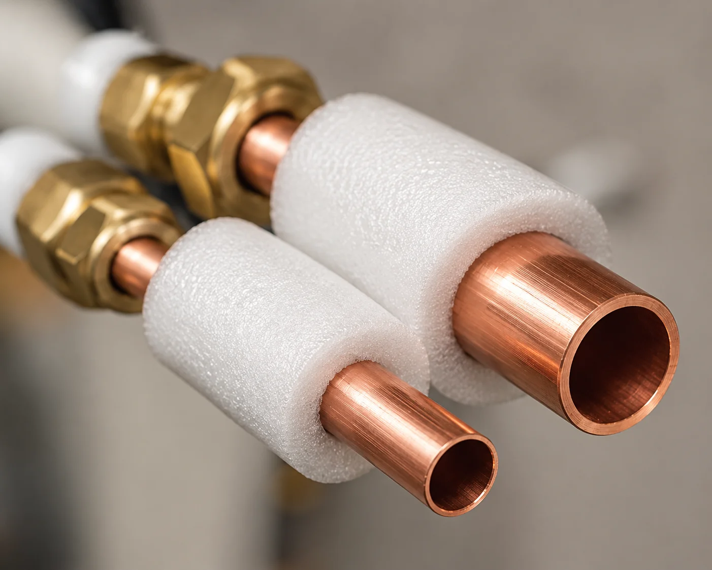
Replacing or specifying an air conditioning coil is not simply a matter of choosing the right size. The metal, tube geometry, fin density, refrigerant, and site conditions all influence capacity, efficiency, and reliability. If any of these factors don’t match, you can get low airflow, high head pressure, short cycling, or premature leaks. This article focuses on copper tube and aluminum fin coils, explaining what to match, what to avoid, and which details can significantly affect performance. You will see how refrigerant type, tube diameter, wall thickness, circuiting, and installation practices interact, along with practical steps for corrosion control, cleaning, and performance monitoring that can help a new coil last.
-
Match the Coil to Refrigerant, Capacity, and Airflow
Start with the basics: evaporator or condenser duty, system capacity, refrigerant type, and available blower airflow. Evaporator coils operate on the low-pressure side and must work with the sysystem’setering device, such as a TXV or capillary tube. Condenser coils operate at higher pressures and release heat outdoors. A coil designed for R-410A must withstand different operating pressures than one designed for older refrigerants. Its internal volume and face area must also support the required capacity at an appropriate airflow rate. An undersized face area can increase pressure drop and reduce moisture removal, while improper coil selection can contribute to poor humidity control and refrigerant distribution problems.
When selecting a copper coil for Ac verify refrigerant compatibility, the number of rows, fin density, and equipment specifications rather than relying on nominal capacity alone. For example, converting an older system from R-22 to equipment designed for R-410A requires components specifically approved for the newer refrigerant and system design. The coil, metering device, blower performance, and other components must work together. A simple capacity match on paper that ignores airflow can lead to ongoing comfort and humidity problems when the equipment operates under demanding conditions.
-
Tube Diameter, Wall Thickness, Fins, and Circuiting: Why Details Matter
Copper tube diameter and wall thickness affect both heat transfer and durability. Common tube sizes may include 5/16, 3/8, and 1/2 inch, depending on the coil design and application. Thinner tube walls may support efficient heat transfer but provide less material to withstand physical damage or corrosion. Heavier walls can provide additional mechanical strength and corrosion allowance, which may be useful in demanding environments.
Fin density, generally expressed as fins per inch, increases heat transfer surface area, but higher density is not always better. In dusty environments, such as commercial kitchens, workshops, or bakeries, closely spaced fins can become clogged more quickly. A moderately lower fin density may make cleaning easier and help preserve airflow, even if laboratory performance appears slightly lower.
Refrigerant circuiting also affects how evenly the coil operates. Different circuit arrangements can influence refrigerant distribution, temperature consistency, and moisture removal across the coil face. Additional circuits and well-designed distributors can improve refrigerant distribution, but they also increase manufacturing and service complexity.
It is also useful to compare traditional copper tube and aluminum fin coils with aluminum microchannel designs. Microchannel coils are lightweight and compact, while traditional copper tube coils may offer different service and repair options. Each design has advantages and limitations depending on the environment, equipment configuration, service access, and expected maintenance requirements. Selection should reflect the actual operating conditions rather than material preference alone.
-
Installation Practices That Make or Break a New Coil
Even a properly selected coil can perform poorly if installers do not follow proper procedures. Refrigerant system work should be performed by qualified HVAC professionals using procedures approved by the equipment manufacturer. Proper brazing practices can help prevent internal oxidation and contamination that could interfere with metering devices or refrigerant flow. Use correct materials and heat protection around valves, painted surfaces, and other temperature-sensitive components.
After completing the connections, evacuate the refrigerant circuit with appropriate equipment, and charge it to match the manufacturer’s specifications. Moisture or other contaminants left inside a sealed refrigerant system can contribute to performance problems and shorten compressor life. A properly selected filter drier may also be required, particularly when the refrigerant circuit has been opened o, or components have been replaced.
The metering device must also match the refrigerant, coil, and equipment design. An incorrect TXV or other metering device can cause unstable refrigerant flow, excessive superheat, or other operating problems. After startup, a qualified technician should verify operating pressures, temperatures, airflow, superheat or subcooling wh(where applicable, and other manufacturer-specified performance targets.
For heat pump systems, the coil, refrigerant circuiting, valves, and controls must also support operation in both heating and cooling modes. Verify defrost controls and other operating strategies as part of commissioning.
-
Corrosion, Chemicals, and Site Conditions
Copper is durable, but its environment can strongly influence service life. Indoors, exposure to certain volatile organic compounds from cleaners, adhesives, building materials, and other products may contribute to corrosion. Good ventilation during renovations and properly sealed return air pathways can help reduce unnecessary exposure of the evaporator coil to chemical contaminants.
Keeping the condensate pan and drainage system clean is also important because accumulated moisture and debris can encourage biological growth, restrict drainage, and affect airflow. Protective coil coatings designed specifically for HVAC equipment may help reduce corrosion in some environments. Still, they should be properly selected and applied so they do not interfere with heat transfer or airflow through the fins.
Outdoor coils in coastal environments face additional challenges from salt and moisture. Salt accumulation can accelerate corrosion on aluminum fins and other components. Proper equipment placement, regular inspection, and manufacturer-approved fresh water rinsing may help reduce buildup in areas with significant salt exposure. Factory-applied protective coatings designed for marine environments may also be appropriate for some installations.
Aggressive acidic or highly alkaline coil cleaners can damage aluminum fins, protective coatings, and other materials if used incorrectly. Follow equipment and cleaning product recommendations and use methods appropriate for the particular coil. Install dissimilar metals, mounting hardware, and contact points correctly to reduce corrosion and prevent vibration-related wear.
-
Maintenance and Early Warning Checks That Pay for Themselves
Airflow is essential to coil performance. Choose filters with a MERV rating that the blower and duct system can handle without creating excessive static pressure. Homes with shedding pets or commercial spaces with significant airborne particles may require more frequent filter inspection and replacement. Inspect the evaporator coil periodically for visible dirt or debris that could restrict airflow.
Cleaning methods should follow manufacturer recommendations. Depending on the coil and level of contamination, professional cleaning may be needed, using approved coil-cleaning products and careful rinsing methods that protect delicate fins. Bent fins can restrict airflow and may require careful straightening using suitable tools.
Inspect suction line insulation and the area around the coil cabinet for deterioration or condensation. Damaged insulation can contribute to unwanted heat gain, condensation, and energy loss.
Performance changes can also provide early warning signs. A noticeable change in the temperature difference between return and supply air may indicate airflow, coil, or refrigerant problems, although temperature readings alone are not enough to diagnose the cause. A ChA-qualified technician should evaluate changes in refrigerant performance, unusual noises, oily residue near connections, or repeated loss of cooling capacity. Leak detection and refrigerant pressure testing require appropriate equipment and training. Addressing a suspected leak promptly can help prevent the system from operating with an incorrect refrigerant charge and reduce additional stress on the compressor and other components.
Protect Coil Performance From Selection Through Maintenance
Choosing the right coil involves a series of connected decisions r, not a single specification. Match the coil to the refrigerant, equipment capacity, and airflow requirements. Select tube dimensions, wall thickness, fin density, and circuiting that suit the operating environment and realistic maintenance conditions.
Installation quality matters just as much as component selection. Proper brazing practices, leak testing, evacuation, charging, and metering device selection all contribute to reliable performance. After installation, protect the coil from corrosive exposure, maintain clean airflow, and monitor the system for early signs of performance changes.
When you manage these factors together, a copper coil can maintain capacity, support humidity control, and provide reliable service for years. Careful selection, professional installation, and consistent maintenance provide a stronger foundation for long-term AC performance.